
Guides
How To Install A Single-Phase Voltage Of 208 Volts?
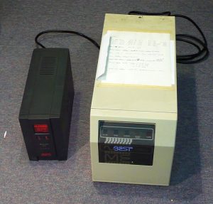
Project designers who want to use an UPS, or uninterruptible power supply, that requires 208V single-phase power should be familiar with the characteristics of 208V electricity and how they interact with various UPS types.
Because it varies depending on the kind of UPS, because it is something that you may not run across on every project, and because it has the potential to be a pricey oversight if it is disregarded, this is one of the topics that generates the most inquiries.
As was said before, this circumstance does not always present a problem. Even though SEPS has designed the standard component numbers to eliminate any possible problems, there are still queries that need to be answered.
The Structure of the Problem
Simply expressed, there is the possibility of a mismatch occurring with certain combinations of UPS model, bypass switch type, and input voltage depending on the specifics of the setup. All of this is due to the characteristics of 208V electricity and the way that transformers have an effect on it.
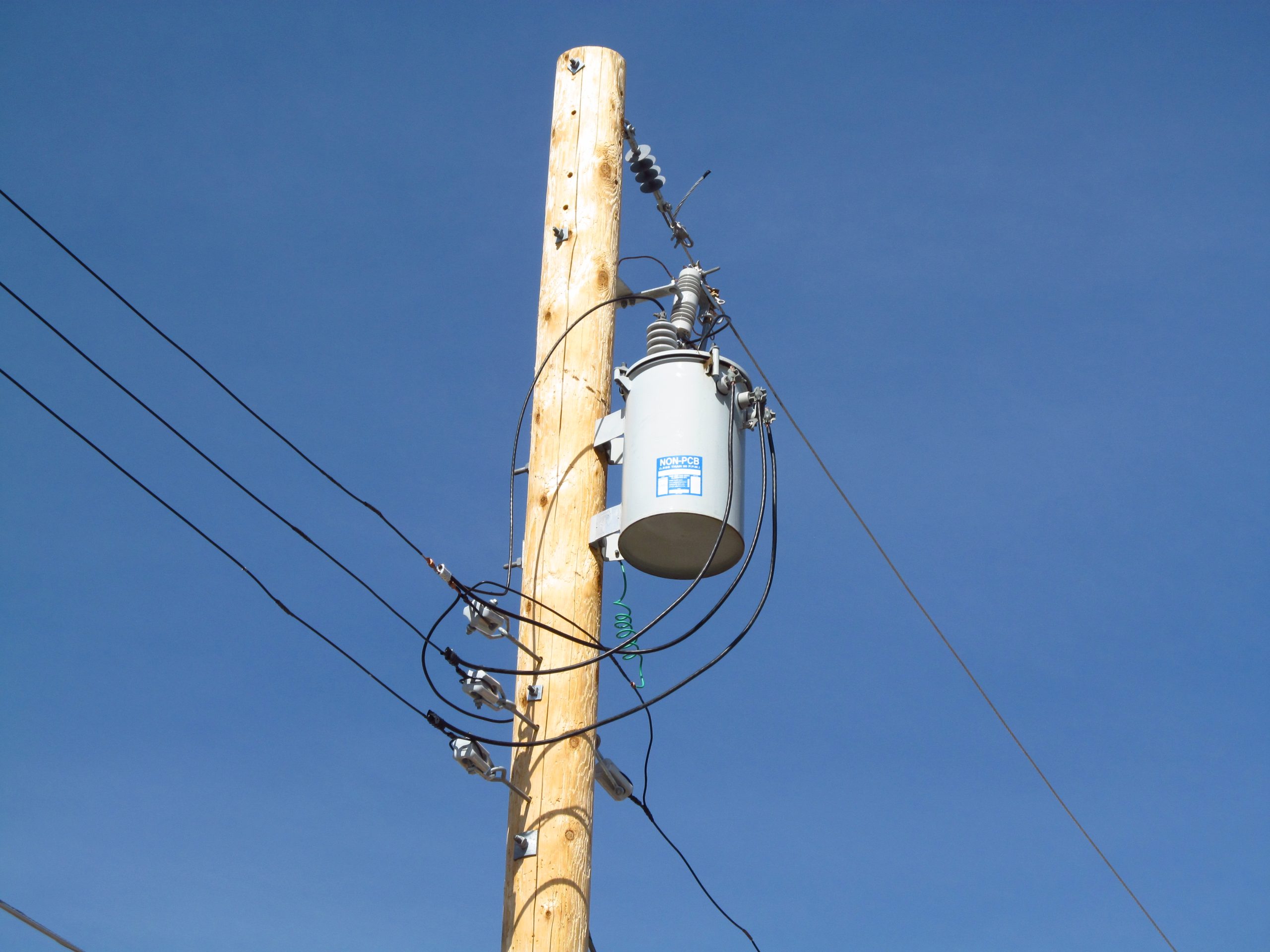
Power at 120/208 Volts, Single Phase
208-volt three-phase electricity is converted into 120/208-volt single-phase power.
When seen on an oscilloscope, the three voltage waveforms that are present on the three conductors that are considered to be “hot” all peak at different times; more specifically, each one is 120 degrees behind the one that came before it.
When working with a single-phase voltage of 120/208 volts, you may utilize any two of those same three hot conductors, but the peaks of the two waveforms must be offset by 120 degrees from one another.
Due to the fact that the peaks of the two waveforms occur at separate times, the total power that you obtain from them is less than the sum of their numerical values.
The voltage measured by one waveform is at its highest point when it is 120V, whereas the voltage measured by the second waveform is just 88V when it is only halfway through its cycle
https://youtu.be/r3hSaiIt8-Y?si=izQPkLkS6Bf84Urt
. The total combined voltage is 208V. If the two waveforms were coincidental, meaning that their maxima occurred at the same moment, then you would, as you would anticipate, be able to achieve 240V by adding the two 120V peaks together.
Make-Before-Break Switches Are Used as A Maintenance Bypass.
In the case that the UPS has to be serviced or replaced, this device will open up a way for the protected equipment to be powered by the utility power in the event that this channel is needed.
It totally disconnects the UPS from the power supply, which eliminates the risk of the service personnel receiving an electric shock while they are working inside the UPS.
This switch is required by Motorola for all hardwired uninterruptible power supply (UPS) systems because it enables the UPS cabinet to be entirely removed and changed without requiring the protected equipment to be powered down.
The Make-Before-Break (MBB) switch overlaps the power on the “UPS” line with the utility power on the “Bypass” line whenever the switch handle is moved.
This brief overlap does not create a problem since it lasts for such a short period of time; yet, it is essential because it allows the switch-to-switch sources without disrupting the operation of the equipment that is being safeguarded.
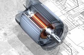
Transformer for removing Signals
This device, which may be an integral part of the UPS or an entirely distinct unit, transforms the electricity from the utility company into power that has been cleaned and conditioned.
In situations in which the power from the utility company is described as “dirty” or “harsh,” you should make use of an uninterruptible power supply (UPS) that has isolation in order to provide your equipment the highest level of protection possible.
According to Motorola’s R56 Standards, uninterruptible power supply (UPS) systems that contain isolation are regarded as independently derived power sources.
(The page titled “Isolation Explained” in this section provides a more in-depth description of isolation transformers; please refer to it for further information.)
According to Kirchhoff’s Law, the amount of power that goes into a circuit must be equal to the amount of power that comes out of it. This includes transformers, in which the power on the primary side (which is the input side) must match the power on the secondary side (which is the output side).
Transformers are only able to manipulate the power that is already there; they cannot “create” new power. If you put 120 volts in, you will get 120 volts out; if you put 208 volts in, you will get 208 volts out; if you put 240 volts in, you will get 240 volts out; and so on.
Putting Everything into Perspective
When electricity with a single-phase voltage of 120/208 volts is fed into an isolation transformer, the two distinct hot conductors of 120 volts are merged into a single waveform of 208 volts.
We need to divide the 208V back into two 120V conductors so that we can power the majority of the Motorola equipment, but this cannot be done since the voltage is too high.
As was said before, the amount of power that is put in must be equal to the amount of power that is taken out without producing anything brand new. Only 208 volts of total voltage are available when the single 208-volt waveform that is coming out of the transformer is divided into two conductors.
Additionally, the peaks of both conductors occur simultaneously. It is impossible for any piece of machinery to make use of the remaining 88 volts of power once one 120-volt wire has been generated.
Because 240V can be divided equally between two 120V conductors, this problem may be solved by setting the output of the UPS to 240V, which is the obvious approach. If there wasn’t a maintenance bypass option for the Make-Before-Break feature, this would be successful.
The electricity from the utility (120/208V) and the power from the output of the UPS (120/240V) are superimposed on one another whenever that switch is activated.
A magnetic “crash” will occur as a direct consequence of the disparity in phase angles between the two voltages, which will cause the circuit breaker that supplies power to the UPS to trip.
Solutions
Since 120/208V input is not possible in isolated UPS systems and the UPS output must be 120/240V to prevent the “88V leg,” the input voltage must be 120/240V. If this is already present at the location, then there is really no need to worry about anything in this regard.
On the other hand, if the voltage at the site that feeds the UPS is 120/208V, you will have to modify it to 120/240V. Both the FERRUPS and the 9170+ UPS systems are capable of achieving this goal in their own unique ways.
FERRUPS
Because the FERRUPS incorporates a ferro resonant transformer as the primary component of its construction, every single model comes included with an internal isolation system.
This indicates that any and all FERRUPS models that might potentially be powered by a 120/208V circuit would be impacted by this issue.
When searching for a FERRUPS model number, it is important to keep in mind that models 3,000W and above may be set up as either 208V or 240V source systems, and you will need to choose the one that is most suited for your needs.
The main difference between the two lies in the fact that the 208V source systems use an external transformer, which brings the input voltage up to 120/240V.
You have the option of using the Break-Before-Make (BBM) maintenance bypass switch rather of the step-up transformer. When the switch is activated, the BBM switch does not overlap the output feeds coming from the utility and the UPS, which results in a power interruption.
Because the electricity will be cut off and any equipment that is still running will be destroyed, it is imperative that any equipment that is protected be turned off first.
Because Motorola maintains the position that the protected equipment should never be turned off, not even for maintenance on the UPS, the BBM is not available in any regular model configurations.
If the external transformer is not a solution that can be implemented, SEPS can provide you with an estimate for a customized configuration.
9170+
For all versions that have a “ISO” appended to its name, the 9170+ comes standard with an external isolation transformer. The output of this external transformer is set to 120/240V, and it may accept electricity at either 120/208V or 120/240V via its various input taps.
Because this transformer supplies the isolation and outputs 120/240V to the bypass switch, none of the two difficulties discussed before is relevant.
Power may be provided to the 9170+ at either 120/208V or 120/240V, depending on whether or not it is fitted with an isolation transformer. All of the problems that were discussed before are resolved when the transformer is not there.
If the location where the UPS will be installed has electricity that is 1220/240V, then you have the option of going with an internal isolation transformer rather than going with an external isolation transformer (for more information, see the component number listings for the Power ware 9170+).
Using this feature makes the 9170+ extremely similar to the FERRUPS, including the 88V leg and phase angle mismatch, therefore it is only accessible with a 240V supply.
SEPS suggests that you do not choose for the internal transformer in order to err on the side of caution if there is uncertainty about the site voltage.


6 Phone Numbers to Call for Music That Still Work (Tested 2026)
In an age of instant streaming on Spotify and Apple Music, the idea of looking for phone numbers to call...


The Ultimate Guide to Modern Bathroom Renovations
The bathroom is no more a simple functional area monitored somewhere in the corner of the house, it has become...


Custom Blinds in Canada: Fit, Finish, and Daily Function
A home is often defined by its windows – the portals that connect our private sanctuaries with the outside world....


Homeowner’s Guide: Practical Tips for Preventing Costly Roof Damage
A home’s roof often sits out of sight and out of mind, so trouble tends to build quietly. Signs appear...


How to Spruce Up Your Home’s Exterior Before Decorating it?
Holiday decorating is always more fun when the stage is set, and nothing sets that stage better than a refreshed...


When Preparedness Becomes a Homeowner’s Best Asset?
What do you do when something at home breaks at the worst possible time? Maybe it’s a leaky roof during...


From Repairs to Renovations: How to Keep Your Home in Top Shape?
Keeping a place in great shape requires attention, time, and smart planning. Small fixes often grow into bigger projects if...


The Most Overlooked Structural Issues in Older Homes
Older homes often carry a charm that newer properties cannot replicate. They offer character, history, and distinctive design. Yet many...


More Than a Change of Address: How to Feel at Home in a New City
Ever unpacked a box of dishes and suddenly felt like a stranger in your own life? It happens. You move...


The Steps That Make Transitioning Into a New Home More Manageable
Moving into a new home feels exciting, yet many people find the process stressful when tasks pile up unexpectedly. A...


How to Tell If Your Water Heater Is Costing You More Than It Should?
If you live in St. Charles, you’ve probably seen your utility bills rise over the past few seasons — even...


Small Space Styling Ideas Featuring the Globule Gold Leafing Console
Small interiors demand furnishings that deliver both style and function without overwhelming the room. The Globule Gold Leafing Console offers...


Budget-Friendly Ways to Modernize an Older Home
If you live in Boulder, you probably know how charming older homes can be. Many of them have character, personality,...


From Cleanup to Care: A Homeowner’s Guide to Storm Recover
Storms can leave families dealing with damaged walls, soaked flooring, and scattered debris. In Northeast Georgia, where strong weather can...


What Are Design Trends That Elevate Homes from Ordinary to Exceptional?
Ever walked into a home that just felt special? It might have been the layout, the lighting, or even the...


Can’t Beat the Chill at Home? Here’s What Might Be Going Wrong
When winter sets in, it often exposes problems in your home you might not have noticed during the warmer months....


Energy-Efficient Home Improvement Projects That Cut Bills
Ever looked at your electric bill in Pennsylvania during winter and thought, “Did I start heating the neighborhood by mistake?”...


Just Moved In? Here’s How to Make Your Home Winter-Ready
Moving into a new home brings a sense of accomplishment, boxes are unpacked, furniture is in place, and the space...


How Coastal Homes Stay Reliable Year After Year?
Coastal homes capture a kind of beauty that few other places can match. Waking up to the sound of waves,...


Your Complete Seasonal Home Tune-Up Checklist: What to Do Every 6 Months?
Seasons come and go, and your home works hard to keep up with the changes. From running your air conditioning...


Energy-Efficient Roofing Solutions in NJ | Yukor Construction
When planning a roof replacement, many homeowners think first about appearance and protection from leaks. But in today’s conditions, a...


Preventative HVAC Care: Avoiding Costly Breakdowns Before They Happen
A reliable HVAC system is essential for maintaining comfort, air quality, and energy efficiency throughout the year. Yet, many property...


If I Unblock Someone on iMessage, What Happens?
In today’s global world, it is necessary to stay in touch with friends, family and colleagues. Apple IMessage service is...


How Smart Pool Cleaners Integrate with Home Automation Systems?
In today’s smart home world, the robot pool cleaner is no longer a utility device but rather is now a smart,...

What Causes an Electric Motor to Hum and not work
One of the most common machines is those that are powered by electric motors. At times, however, these motors can...


How to Find Your Verizon Account Number
Introduction So Verizon is a popular messaging service and calling app that provides the option of free call and phone...


How to Delete Read-Only Contacts: Android & iphone
Introduction It is simple to delete read-only contacts on the Android and iPhone but a question arises here: how can...


How to Find Saved Videos on My Phone
Introduction Nowadays the integral part of our life is the mobile phone. We create so many memories everyday and store...


You Can’t Message This Account: Messenger Fixed
Introduction Facebook messenger is one of the most popular messaging apps globally to connect with other people throughout the world....


Delete Text Messages on iPhone for Both Sides
Introduction It is simple to delete messages on the iPhone but a question arises here: how can we delete messages...


Why Won’t My Call Go Through to a Certain Number?
Introduction In today’s fast-paced world, staying in touch with everyone is important. For this purpose, we use our phone to...


Call Ends Immediately After Dialing on Android
Introduction In today’s fast-paced world, staying in touch with everyone is important. For this purpose, we use our phone to...


What Is Logitech Download Assistant?
Logitech is famous throughout the world for their amazing computer accessories including mouse, keyboard and headsets. These devices come with...


Does a Canceled Call Go Through on iPhones?
Introduction In today’s digital world there are new and exceptional ways for connecting with each other. Communication has also evolved...


How to Create an INI File on Windows, Mac, Android
Introduction The files that are used to store settings and configuration for the software application are known as INI files....


How Long Do AirPods Take to Charge from Dead?
Airpods Pro are one of the best and most popular airbords that are wireless and available in the market nowadays....


PS4 Controller Charging but Not Connecting
Introduction Many people play PS4 games nowadays but sometimes they encounter a frustrating issue which is that their controller is...


How to Fix IMS Registration Status Not Registered
Introduction IMS stands for IP multimedia system which is present in carrier rn smartphones that play a crucial role in...


Rythm Discord Bot: What It Is and How to Use It
Introduction Discord has been extremely popular nowadays aur communication among gamers technicians and other communities that want to stay connected...


Where Is the Volume Button on a Vizio TV
Introduction It is easy to find the volume button on the Vizio TV but it can be difficult for a...


Smart Travel Hacks by CWBiancaVoyage: Your Ultimate Guide
Introduction Traveling can be both exhilarating and overwhelming. Whether you’re a seasoned globetrotter or a first-time explorer, the journey often...


Call Error: “The Number You Are Trying to Call Is Not
Introduction Few things are more frustrating than dialing a number only to hear the automated message: “The number you are...

Marketing Automation: A Complete Guide to Smarter Growth
Introduction In today’s digital marketplace, speed, personalization, and efficiency are no longer optional—they are essential. Marketing automation has emerged as...

Do Smart Plugs Use Alot Of Electricity?
In addition to the fact that they are more convenient, smart plugs are intended to help you save money by...


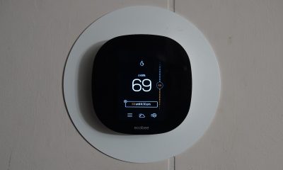
How to Adjust The Temperature On ECOBEE Smart Thermostat?
The Ecobee Smart Thermostat is an advanced piece of equipment that can effectively substitute for your old thermostat. It may...


Top Cheap Gaming Monitors On A Budget
Introduction It is difficult to find a gaming monitor that is affordable and also of great quality. But today the...


Subscriber You Have Dialed is Not in Service
Introduction In today’s fast-paced world, staying in touch with everyone is important. For this purpose, we use our phone to...


What to Do if Spectrum Internet Keeps Dropping, Cutting, Going Out
Introduction It is easy to find the dropping, cutting, going out problem on the Spectrum internet but it can...


How to Sign Into iMessage on iPhone
Introduction In today’s global world, it is necessary to stay in touch with friends, family and colleagues. Apple IMessage service...


The Top 10 Belts for Ab Exercises
You will need to follow a regimented eating plan and training program to get abs like a washboard. However, in...


10 Best Smart Plugs For SAMSUNG Smart Things.
Smart plugs have the potential to have a major effect homes beyond initial expectations. These devices are engineered to enhance...


How To Link An Older Bose Sound System To A Newer Television?
Bose systems are used in the development of high-quality sound systems as well as portable electronic gadgets. Many different Bose...


10 Best Apps To Control All Your Smart Home Devices.
10 Best Apps To Control All Your Smart Home Devices are the kinds of smart home gadgets that used to...


Smartwatch Features: A Comprehensive Overview of Their Capabilities
Trying to choose the perfect smartwatch may be a daunting task, as you’ll want to find one that satisfies your...


Are Smart Locks Hard To Install Find Out Here?
There are several compelling reasons why installing smart locks in a home may be a very worthwhile investment. You won’t...


10 Most Cutting-Edge TVs with Touch Screens
A touch screen TV is a kind of television that can be controlled by touching the screen. This cutting-edge innovation...


How Many Smart Devices Can You Connect To Alexa?
The more gadgets you connect to Alexa, the higher your home’s intelligence will be. Connecting Alexa-enabled smart home devices like...


How To Make Smart Bathroom By Using 5 Gadgets?
The world we live in is completely immersed in advanced technology. Technology makes life simpler in every aspect, from cellular...

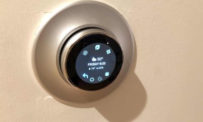
Interesting Things About Ecobee Firmware Upgrades.
All smart devices, including smart thermostats, need periodic software upgrades. Firmware is the term used to describe the software that...


What Is Lg Tv Plus And How Its Works And How To Connect To Tv?
When it comes to Smart TVs, LG is a top contender. The two most common brands of televisions are LG...
-
Gadgets2 years ago
10 Best Apps To Control All Your Smart Home Devices.
-
 Gadgets3 years ago
Does Nest Thermostats Contain Cameras Or Microphones? Is It Safe For you?
-
Guides4 months ago
6 Phone Numbers to Call for Music That Still Work (Tested 2026)
-

 Gadgets3 years ago
What Is The Purpose Of Red Button On The SimpliSafe Keypad?
-

 Gadgets3 years ago
Complete Guide About Equalizer settings for Samsung-Soundbar
-

 Accessories3 years ago
Can Siri Control Samsung Televisions And Are Samsung TVs Homekit Compliant?
-

 Accessories3 years ago
Blink Camera’s Temperature Sensor Settings, and More
-

 Accessories3 years ago
Can Ring Cameras and Other Ring Devices Be Connected to Multiple Networks?